Transformers for Ham Radio
This is a simplified, "real-world," quick reference guide to transformers used in ham radio. There tends to be a lot of confusion and opinions about this topic, including terminology that is continuously used interchangably when it probably shouldn't be! Hopefully this guide will be a helpful and clarifying reference. But there are thousands of articles and YouTube videos that are helpful for further study.
1. Transformers for Antenna Builds
For making antennas, the name of the game is impedance matching. The radio wants 50 ohms. The quest is to get antennas to match that magic number. For simple balanced antennas like dipoles, they are already close enough for rural work. But for more complex antenna builds, this won't be the case. Transformers will help us achieve a good match that the radio requires.
"Transformers" in this context are iron ferrite cores wrapped with specific wire winding patterns. These windings give the ratios of electrical transformation. The iron core helps sustain the magnetic field that is created as current passes through the wire and helps facilitate the impedance change. Terms like "Balun" and "UnUn" are used to describe this too.
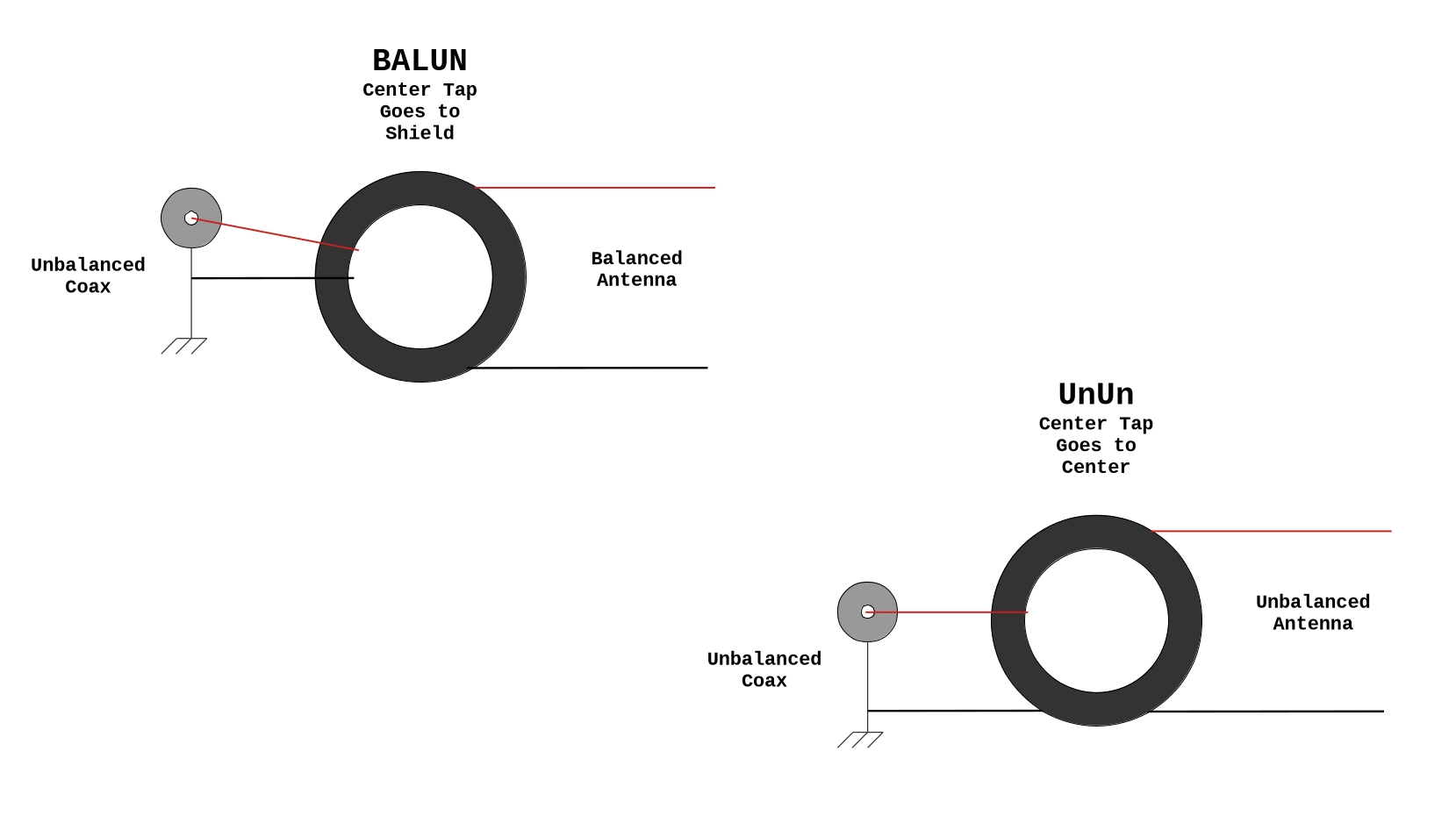
- BALUN: describes a BALanced to UNblanced relationship. As an example, a balanced antenna like a dipole being fed by an unbalanced feed line like coax. Generally, these devices are installed at the junction where the feed line meets the antenna.
- UNUN: describes a UNbalanced to UNbalanced relationship. As an example, an unbalanced antenna like a vertical being fed with coax.
To complicate matters further, there are both Current Baluns and Voltage Baluns. The difference is that current baluns want to force equal currents to the antenna, while voltage baluns want to force equal voltages. For ham radio, current baluns are generally preferred.
Some of these transformer ratios and uses are:
Chokes:
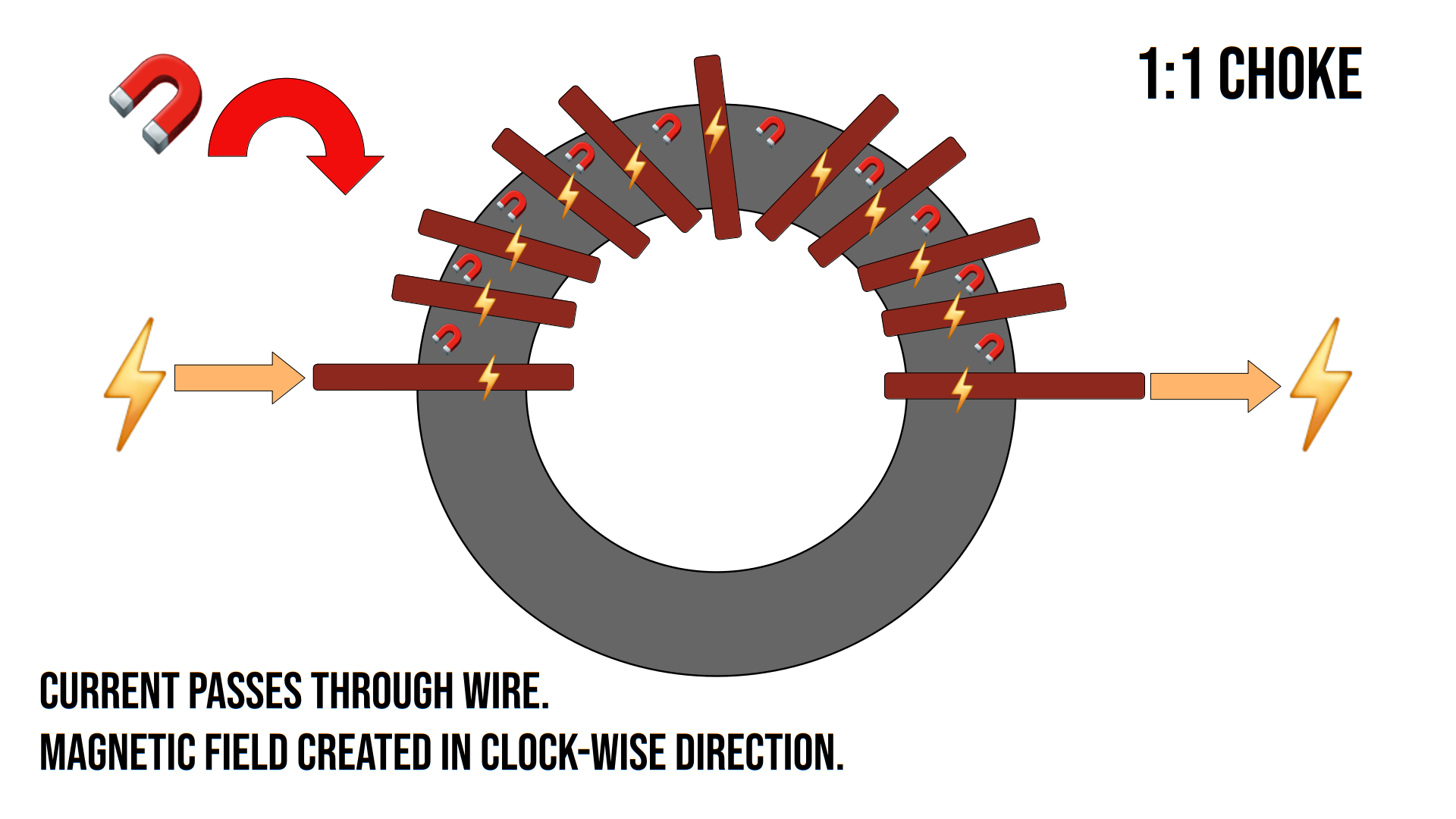
- 1:1 Ratio - used as a "choke" for suppressing radio frequency interference and common mode current (see section 2 below).
Non-Resonant/Non-Symmetrical Antennas:
- 4:1 Ratio - 200 ohms impedance transformed to 50 ohm.
- 4:1 Current Baluns are used for Off-Center Fed Dipoles, Delta Loops, etc.
- 4:1 UnUns can be used for random wire antennas like the Rybakov
- 9:1 Ratio - 450 ohms impedance transformed to 50 ohms - used for Random Wire Antennas.
Resonant Antennas:
- End Fed Half Wave Antennas - these use a variety of ratios
- 36:1 (1800 ohms), 49:1 (2450 ohms), 56:1 (2800Ω), 64:1 (3200Ω), 81:1 (4050Ω) - Any of these ratios can work for your antenna needs. 49:1 is a classic ratio for a resonant, multi-banded antenna that gives you 40m, 20m, 15m and 10m on a 66' wire. Similar results can be achieved with the other ratios with the addition of coils in the antenna wire at specific locations. 56:1 is a stellar performer for mono-band EFHWs. 81:1 works great for a 40m NVIS antenna that is close to the ground.
2. Chokes and Interference
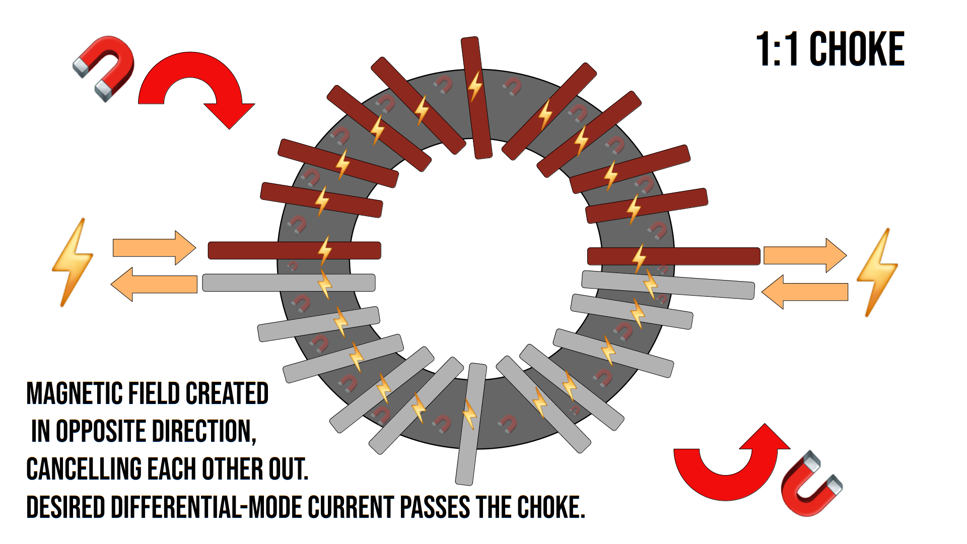
You can build a resonant, balanced antenna like a dipole, put it up and operate with no issues. However, the concept of "Common-Mode Current" can be problematic. Ideally, with a balanced antenna and feedline system, you would have equal and opposite currents that would cancel each other out. In real life, this is hardly ever the case. A portion of the current can "go rogue" and flow back down on the outside of the coax braid, back to the rig, back to the shack, and cause havoc. This makes the feedline radiate or become part of the antenna. It can increase noise, Radio Frequency Interference (RFI), RF zaps or burns through the microphone, as well as skew the radiation pattern of your antenna.
We don't want any of these negative outcomes from CMC. So the best solution is to always use a "choke" to knock down the common mode current to an unnoticeable level. It "chokes" the CMC out and "isolates" components, like the antenna or the feedline, depending on where it is installed. But what is the choke exactly?
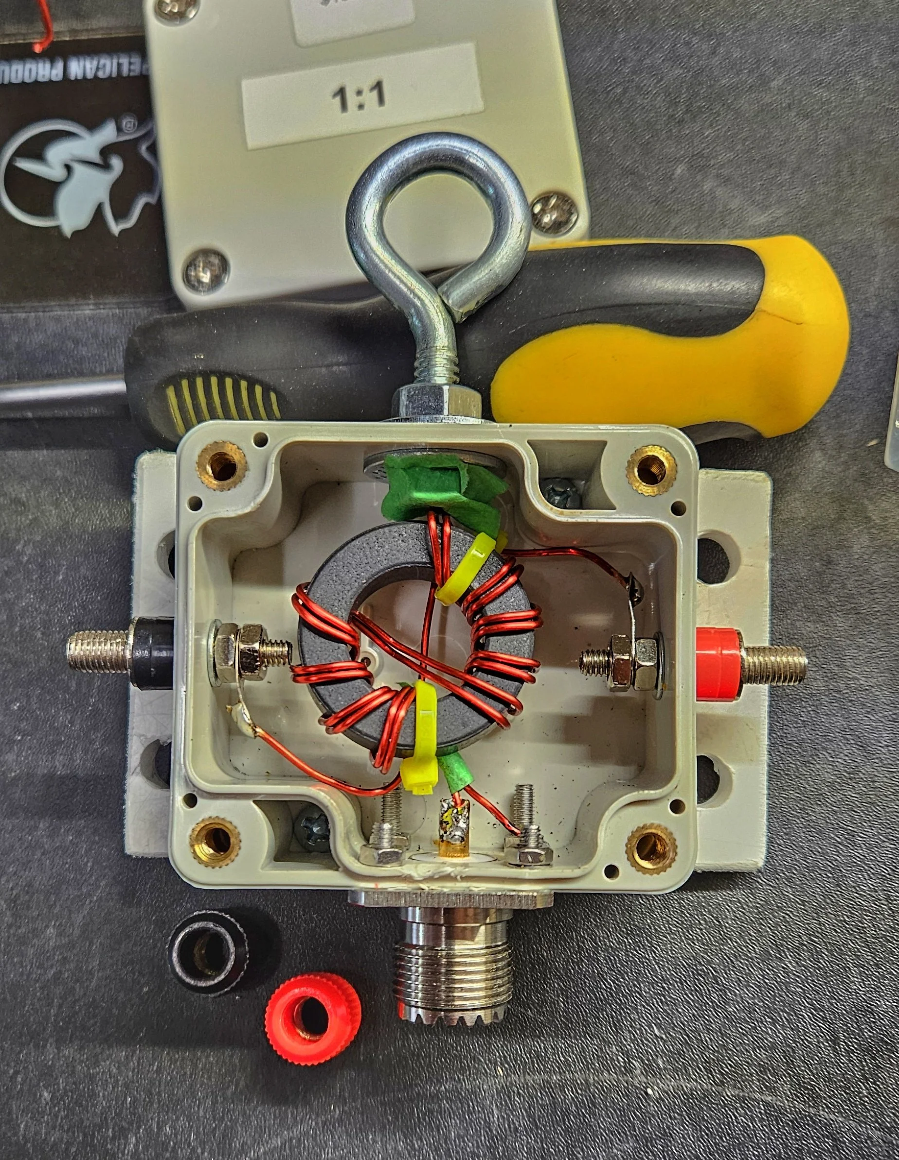
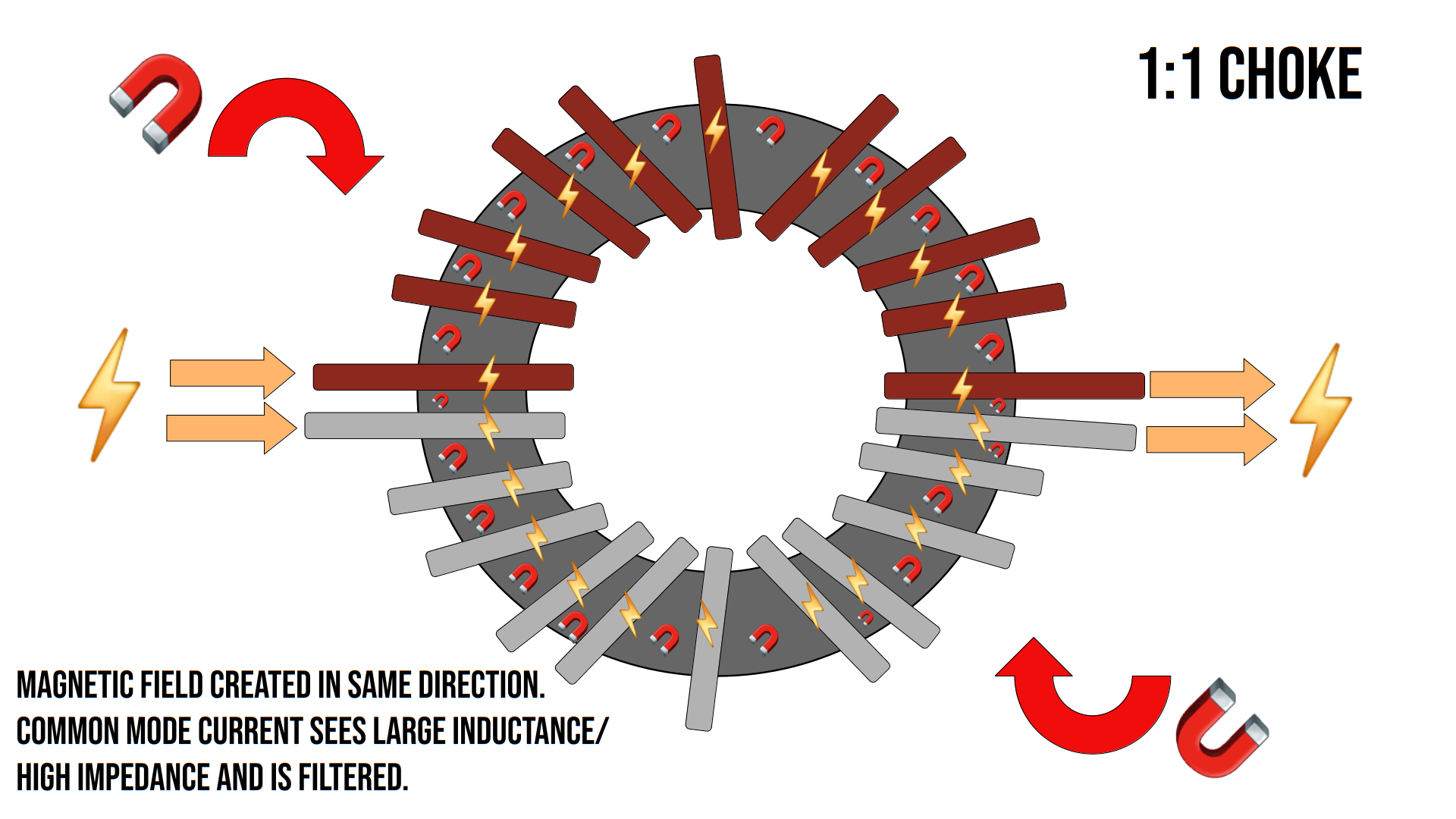
Simply put, the choke creates a high-impedance for the CMC and blocks it from flowing. It's kind of like a one way valve. It allows current to flow in one desired direction - out to the antenna and not back to the shack. This can be accomplished in a few different ways. Ferrite beads can be added to coax and shack components. Also a "balun choke" can be used: a toroidal core with a 1:1 winding pattern.
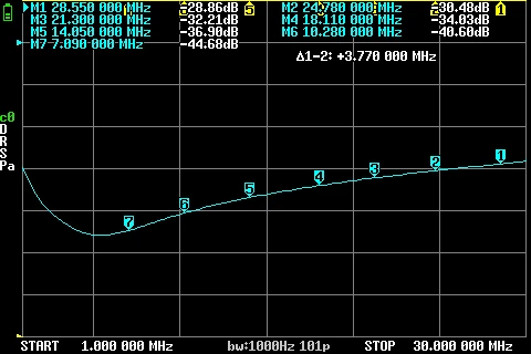
This is a NanoVNA sweep of a type 43 1:1 choke. You can see that it offers -44dB - -28dB of attenuation across the 40m through 10m bands. Generally, -30dB is considered good performance so this particular choke is doing an excellent job.
3. Core Choices
Iron ferrite cores are made of different "mixes" for different purposes in electronics. For ham radio, there are a couple of notable mixes:
- Type 31: great choice for making chokes.
- Type 43: great choice for chokes and transformers.
You can buy these ferrite cores from online retailers like DigiKey, Mouser, Amazon, etc. They are generally known by their part numbers. For example, 5943003801 is the part number for a type 43 mix toroid made by fair-rite and has an outside diameter of 2.4"(61mm). The mix type is embedded into the part number. Realize that there is a difference between these ferrite cores and iron powder cores that are often red or yellow in appearance.
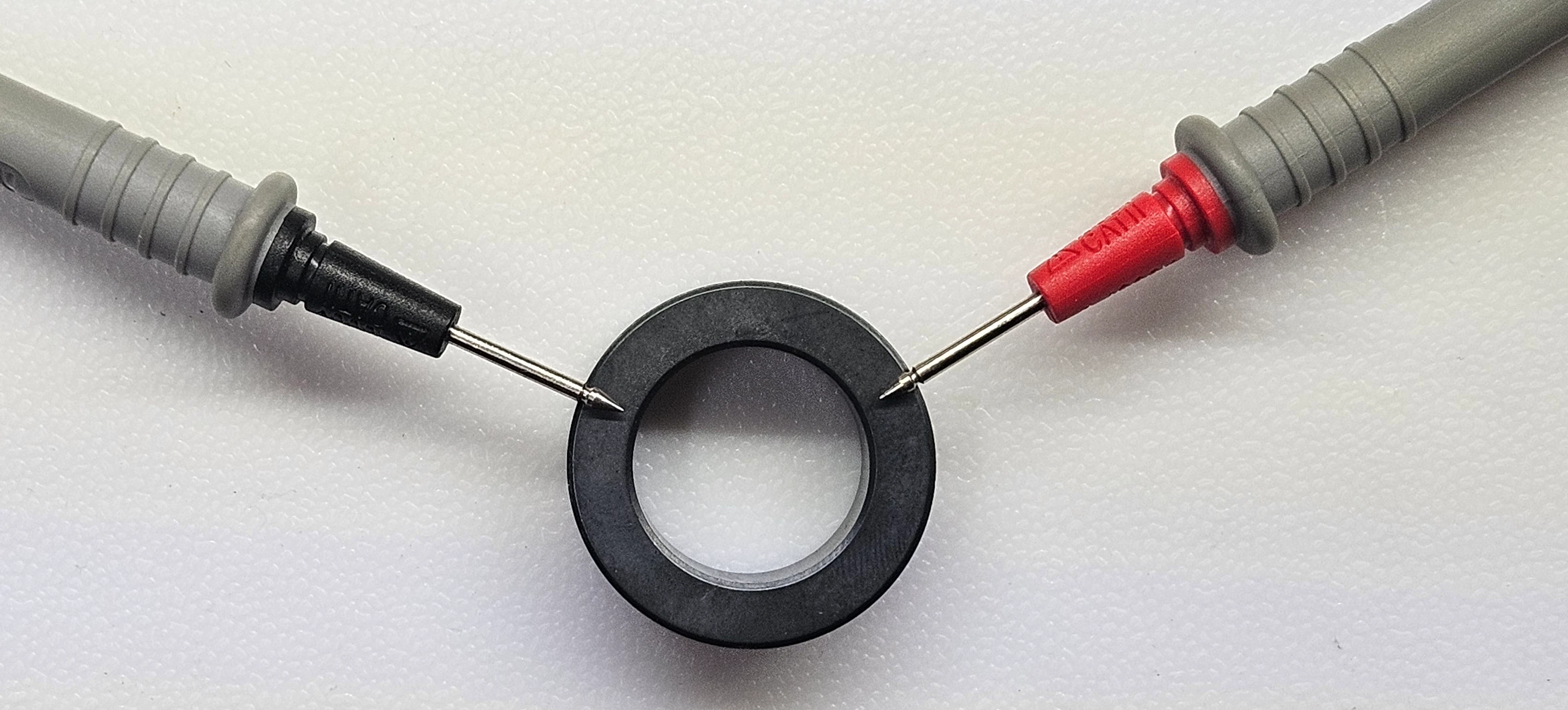
Tip: you can identify unknown core types with just a multimeter. Probe across the core material.
- Types 31, 77, 78 have high resistivity and will have some reading on a meter
- Types 43, 52 and 61 have low resistivity and will have no reading on a meter
The following list is recommended core choices that we have used personally with great results. Links go to our test results:
- Type 31 - for chokes only. -30dB attenuation 80m-15m bands, slightly less 12m-10m.
- Size: 1.142" (29.01mm) OD. Core: 2631801202 [$2.13 in 2025]
- Size: 2.4" (60.96mm) OD. Core: 2631803802 [$13.15 in 2025]
- Type 43 - for both chokes and transformers. -30dB attenuation 80m-10m, slightly more 80m-40m.
- Size: .827" (21mm) OD. Core: 5943000601 [$2.09 in 2025]
- Size: 1.4" (35.55mm) OD. Core: 5943002701 [$4.85 in 2025]
- Size: 2.4" (60.96mm) OD. Core: 5943003801 [$16.07 in 2025]
- Size: 1.540" (39.12mm) OD Core: 2643251002 [$12.22 in 2025] - VE5REV Recommended core for transformers!
- Type 61 - best for multi-ratio transformers.
- Size: 1.020" (25.91mm) OD. Core: 2661102002 [$8.33 in 2025] - VE5REV Recommended core for compact builds!
- Also, due to the higher temperature rating, this core may be a better performer for digital modes like FT8.
- Colin, MM0OPX - Efficiency Comparisons
- Jan, DG1JAN - More Efficiency Comparisons
- Dipoles, Verticals, Beams:
- Antenna Feedline junction
- Optional also at the rig
- Random Wire:
- Between the 9:1/4:1 transformer and the feedline
- Optional also at the rig
- EFHW:
- At the rig only if you want to use the coax as counterpoise
- Transformer Feedline junction if using a dedicated counterpoise
- Optional at the rig for noise
- Measure a 1:1 Choke - TheSmokinApe
- Calibrating test leads for the NanoVNA - TheSmokinApe
- Chokes and Baluns - DX Commander
Note: These recommendations are likely to change as new cores are developed and tested in the future. However, these recommendations stand as they have been proven first-hand in real-world deployments.
Other hams have done amazing work researching cores and have compiled their data to share:

4. Wire Choices
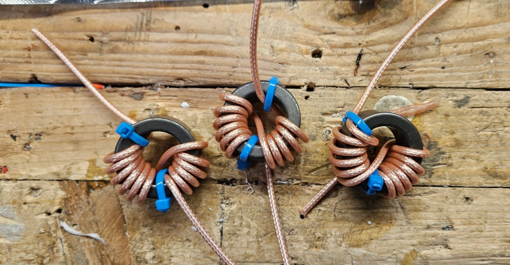
The wire used to wrap toroids is a consideration that can affect performance. The general recommendation is that enamel/magnet wire is best for use in transformers while Teflon (high temperature) wire is preferred for chokes. Enamel wire is not recommended for chokes due to greater losses from proximity effect - an increase in resistive line loss, similar to skin effect. 50 Ohm Coax will provide the most consistent results for chokes. Bifiliar windings can introduce inductive reactance which will affect the higher HF bands. We recommend using coax to make chokes. Teflon insulated wire is gaining in popularity for chokes due to the higher temperature rating of that wire. Gauge can be adjusted depending on ferrite core size.
Power Rating. Good data is rather difficult to find on this topic. There aren't really any industry standards to go from. Palomar Engineers, a well respected vendor of ham radio products, sells a 1:1 choke kit based on a 2.4" (F240) ferrite core and 2 'insulated' wires and says it is rated for up to 1500w! But even this kind of rating can be relative as baluns lose ~40% of their power rating at SWR of 2:1 and 60-70% at 3:1. Further to this, digital modes like FT8 that hammer the toroid with 100% carrier for the full transmit cycle can cause the toroid to heat up. It may not have time to dissipate heat between transmissions which can cause the SWR to go crazy when the core becomes saturated. Hence, if there is an SSB rating given, digital and CW modes are often 50% and 25% of that SSB rating.
5. Choke Placement
This is highly dependent on your antenna system. Sometimes you want the choke at the rig before the feedline. Sometimes you want it at the junction where the antenna meets the feedline. Somtimes you may want both! The choke will stop the CMC and 1) isolate the antenna for correct radiation and 2) eliminate noise at the rig. Here are some placement recommendations:
6. Further Information
There is an incredible corpus of quality, well researched work available on this topic from Jim Brown K9YC. This link has numerous resources available. The following resources are particularly helpful:
YouTube Resources:
VE5REV 73!